
A comprehensive technical overview of single-die sheet metal forming mechanics, polyurethane elastomer selections, and fluid cell press capabilities.
Rubber Pad Forming (Elastoforming) is a sheet metal cold stamping process that uses a flexible elastomer—such as natural rubber or high-strength polyurethane—as a universal lower or upper die. Unlike traditional dual-metallic tooling that requires high-precision matching between a “rigid male die and rigid female die,” rubber pad forming requires only a single-sided rigid half-die (typically a male punch). It leverages the near-liquid incompressibility of the elastomer contained within a closed vessel under extremely high pressure to wrap and conform the sheet metal tightly around the half-die profile.
How does a flat sheet of metal transform into a complex 3D contoured surface without a traditional rigid upper die? This is precisely the problem solved by rubber pad forming.
In conventional stamping, metal sheets are typically placed between matching rigid dies. The punch descends while the cavity die supports and constrains the material—two metal tools with fixed geometry jointly dictate the final part shape. Rubber pad forming alters this fundamental tooling setup: while the part’s geometry is still defined by a rigid form block, the matching metal punch on the opposite side is replaced by an elastomer pad capable of significant elastic deformation. As the hydraulic press compresses the rubber(Typically polyurethane) pad, the pad transmits the load to the metal sheet, forcing it to gradually conform to the working surface of the rigid tool.
Therefore, rubber pad forming is far more than simply “replacing a punch with rubber.” It fundamentally changes the mechanical interaction between the sheet metal and the forming tools. While a rigid punch directly forces the material through its own fixed geometry, the rubber pad actively participates in forming through compression, deformation, and force distribution. It is precisely the introduction of this flexible tool that allows a single rigid die to fulfill functions traditionally requiring a paired double-die setup.
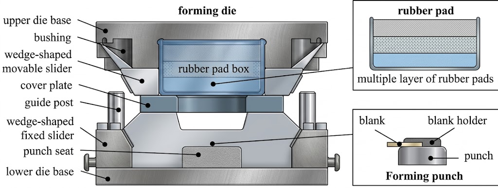
By significantly reducing tooling costs, shortening production lead times for low-volume runs, and protecting metal surfaces from scratching during the forming process, this technology is widely applied in aerospace, defense, automotive prototyping, and high-end architectural cladding, among other sectors.
Evolution and Development of the Process
Rubber pad forming is generally categorized under flexible die forming technology. In the late 1930s, Henry Guerin developed a class of rubber pad forming methods—later known as the Guerin processNote 1—and applied them to the manufacturing of aircraft structural components. The aerospace industry provided an ideal application environment for this process: parts frequently featured complex contoured surfaces, materials were predominantly lightweight metals such as aluminum alloys, and production volumes for individual components were often limited. Fabricating a dedicated set of precisely matched rigid punches and dies for every single part would result in significantly higher tooling costs and substantially longer manufacturing lead times.
Rubber pad forming introduced an alternative approach. As long as a single rigid form block is manufactured to define the part’s final geometry, a reusable elastomer can serve as the flexible tool on the opposing side. When a part design changes, typically only the rigid form block defining the geometry needs modification, eliminating the need to concurrently produce a brand-new set of fully matched upper and lower dies. With advancements in hydraulic equipment, elastomer materials, and process control technologies, rubber pad forming gradually expanded from early aerospace manufacturing into automotive prototyping, industrial equipment, rail transit, and other low-volume production sectors requiring complex sheet metal parts.
The Forming Journey: From Flat Sheet to Contoured Surface
The rubber pad forming process typically originates with a flat sheet metal blank. The working surface of the rigid form block establishes the final contoured surfaces, recesses, flanges, or other geometric features that the part must adopt. The sheet metal is positioned above or within the working zone of the form block, with its exact location and constraint method dictated by the component’s geometry.
For certain parts, the sheet edges must be clamped or blank-held to regulate material movement; for other configurations, a degree of sheet sliding during forming must be permitted. Whether material can flow freely and how that movement is constrained directly impacts the strain distribution within the sheet. Consequently, rubber pad forming is not a process dictated solely by applied pressure—boundary conditions play an equally critical role.
The rubber pad is situated on the opposite side of the sheet. It can be housed within a rigid container or constrained via other structural arrangements. Once the hydraulic press begins applying a load, the rubber pad initially undergoes compression in the zone contacting the sheet. As the stroke increases, the pad’s deformation zone progressively expands, causing the sheet to begin bending from its initial flat state.
Plastic deformation rarely occurs uniformly across the entire sheet simultaneously. Forming typically initiates through localized contact and bending, subsequently propagating to adjacent regions. After making contact with the tool’s fillets and radii, the material continues moving along the die contours, undergoing further bending and stretching along sidewall areas. When the applied pressure and displacement reach adequate levels, the sheet progressively conforms to the main working surfaces of the form block.
From a macro perspective, the rubber pad might appear simply to push the sheet against the form block. In reality, however, the sheet simultaneously experiences bending, stretching, localized compression, and material flow. The magnitude of deformation varies across different regions. Tool radii, depth variations, boundary constraints, and frictional conditions all actively alter the material flow path.
This explains why identical materials and sheet thicknesses can yield vastly different forming results across different part geometries. A component featuring generous radii and gentle contours may form smoothly at lower pressures, whereas a similarly sized part with deep, narrow channels or tight corner radii might demand significantly higher pressure—or even an entirely modified process route.
Machinery Selection: Looking to implement these forming principles into your production line? Explore technical specifications, tonnage capacities, and cycle configurations for BITAERON High-Pressure Rubber Pad Forming Presses.
What the Rubber Pad Actually Does During Forming
The key to understanding rubber pad forming lies in grasping how an elastomer transmits load.
A metal punch has a fixed, rigid shape. When it exerts force on a sheet metal blank, pressure is primarily transferred through its static, unyielding surface. A rubber pad operates under a completely different mechanism. Under compression, it undergoes substantial deformation, allowing its working surface to dynamically adapt to the changing geometry of both the form block and the sheet metal. Consequently, rather than pushing the material with a pre-machined, fixed contour, the rubber pad continuously alters its own shape throughout the forming stroke.
Polyurethane is one of the most widely used elastomeric materials in rubber pad forming. When subjected to compression, an elastomer’s volumetric change is typically negligible compared to its shape change. Constrained within a housing, the rubber pad can undergo large-scale elastic deformation, transferring external hydraulic loads directly to the contacting sheet surface. Because the rubber pad lacks the rigid, defined geometric boundaries of a steel punch, its pressure application zone expands and shifts dynamically in tandem with its deformation.
In engineering discussions, the behavior of a rubber pad under confined compression is sometimes analogized to fluid pressure transmission. While this analogy provides a helpful mental model for understanding pressure distribution, rubber is not a true liquid. In practice, the localized pressure actually applied remains heavily governed by the elastomer’s durometer (hardness), thickness, shape, confinement configuration, and degree of deformation.
Frictional conditions at the pad-to-sheet interface also significantly alter the forming dynamics. While the normal force (perpendicular to the sheet surface) drives the material toward the form block, interfacial friction determines whether the sheet can slide freely. Higher friction restricts material flow in localized zones, whereas lower friction enables better material redistribution. As a result, lubrication conditions and surface finishes directly dictate final forming quality in real-world manufacturing.
Sheet Deformation: Far More Than Simply “Pressing Down”
Sheet metal deformation in rubber pad forming must be evaluated through several interconnected mechanics.
In the fillet and corner radii zones of the tool, the sheet initially undergoes pure bending. As the sheet conforms to the tool contour, its neutral axis, inner surface, and outer surface experience varying degrees of tension and compression. For generous bend radii, this deformation progresses smoothly; however, as the radius sharpens, localized strain increases dramatically.
For components requiring significant depth, the material must undergo further displacement along the tool contours. Certain regions primarily experience bending, while others are subjected to severe tensile stretching. When edge constraints limit free material flow, plastic strain in localized zones can escalate even further.
If the localized strain sustained by the material exceeds its forming limit, cracking or fracturing will occur. Conversely, if the sheet is subjected to improper constraints under compressive stress, instability and wrinkling will develop. Therefore, the uniform pressure provided by a rubber pad does not automatically eliminate all forming defects. Material ductility, part geometry, and boundary conditions still fundamentally dictate the ultimate forming limit.
This highlights a critical distinction in rubber pad forming: it is not a process where “higher pressure is always better.” While ramping up tonnage can improve conformance in stubborn geometry, if localized over-straining has already occurred, additional pressure cannot alter the intrinsic forming limits of the material—and may instead exacerbate wall thinning, cracking, or premature rubber pad failure.
Material Selection Defines Process Limits
Material characteristics fundamentally dictate the boundaries of rubber pad forming. The process is best suited for sheet metals possessing adequate ductility. Aluminum alloys represent the most prevalent material class, particularly in aerospace and lightweight structural manufacturing. However, forming capabilities vary significantly across different aluminum alloys, where chemical composition, heat treatment temper, and yield strength directly govern the sheet’s capacity for plastic deformation.
Even within the same aluminum grade, differing heat treatment tempers can yield vastly contrasting forming behaviors. Softer tempers generally exhibit superior ductility, whereas high-strength tempers—while capable of sustaining higher operational loads—present a much greater propensity for cracking and springback. Consequently, material grade alone is insufficient to confirm process feasibility.
Low-carbon steel exhibits favorable plasticity and can also be effectively processed via rubber pad forming. Compared to aluminum alloys, steel typically demands higher forming loads, but its inherent material ductility affords a broader processing window for complex deformations.
Austenitic stainless steels present a more intricate scenario. Although possessive of high ductility, their high initial yield strength and pronounced work-hardening characteristics can cause forming loads to escalate substantially. As plastic deformation progresses, the material’s resistance to flow continues to increase; thus, forming load trajectories cannot be reliably estimated solely from initial yield strength.
Titanium alloys demand an even more cautious approach to process design. Certain titanium alloys display high strength and severe springback tendency at room temperature, making their formability acutely sensitive to alloy grade and heat treatment condition. In specialized applications, warm or hot forming is employed to reduce required deformation loads and enhance plasticity. However, elevated-temperature operations extend beyond simple extensions of ambient-temperature rubber pad forming—they necessitate a holistic redesign encompassing material temperatures, elastomer thermal limits, and press structure.
Therefore, evaluating whether a material is suitable for rubber pad forming extends far beyond looking at yield strength. Elongation, strain hardening, sheet thickness, bend radii, draw depth, and temper condition collectively alter the ultimate outcome.
Sheet Thickness and Component Geometry
Sheet thickness influences nearly every critical mechanical factor during forming. Thin sheets bend with greater ease and require lower overall forming loads, but they exhibit reduced resistance to structural instability. When forming complex contoured geometries, thin sheets are inherently more susceptible to localized wall thinning, wrinkling, or geometric distortion.
Thicker sheets possess higher flexural rigidity, enabling them to better retain part geometry; however, they necessitate significantly greater forming loads to achieve full plastic bending and deformation. As thickness increases, tool radii and press capacity become increasingly paramount.
Similarly, component depth cannot be evaluated in isolation from geometry. Two depressions of identical depth—one featuring generous, gradual radii and the other incorporating narrow, deep cavities with tight corner radii—will place drastically different demands on the material.
In rubber pad forming, generous radii favor gradual material deformation. Conversely, sharp corners and tight radii induce severe strain concentration, escalating the risks of fracturing and localized thinning. Undercuts, deep-and-narrow channels, and geometries requiring precise localized backing also exceed the adaptive capabilities of a standard flexible elastomer pad.
Component design is inherently an integral element of the rubber pad forming process itself. Success often hinges not on whether the hydraulic press is sufficiently large, but rather on whether the part geometry permits the material to deform along a mechanically sound path.
Hardness and Thickness of the Elastomer Pad
The rubber pad is by no means a generic component chosen arbitrarily. Its durometer (hardness) directly influences pressure transmission and deformation behavior.
A softer rubber pad accommodates large localized displacement and easily conforms to intricate contours and subtle geometric variations. However, under elevated loads, softer elastomers experience excessive deformation and rapid surface wear. Conversely, a harder rubber pad offers superior load-bearing capacity and dimensional stability, though its compliance with complex contours is diminished.
The pad thickness must likewise be tailored to the form block and component profile. A thicker rubber pad provides greater deformation headroom, delivering fuller flexible compensation during the forming stroke, albeit at the cost of requiring a longer stroke. While a thinner pad occupies less daylight space, it may fail to fully wrap complex tool contours and runs the risk of localized over-compression.
Hardness and thickness are thus interconnected process parameters. They cannot be determined in isolation from forming pressure, tool height, sheet thickness, and component geometry.
Forming Pressure and Hydraulic Press Capacity
The required forming pressure in rubber pad forming is dictated by the plastic deformation demands of the sheet metal. Low-strength, thin-gauge materials may achieve full conformance to the tool at relatively low pressures. Conversely, high-strength alloys, thicker plates, or complex geometries necessitate substantially higher operational pressure.
Crucially, the rated tonnage of a hydraulic press does not equal the actual forming force required by the workpiece. Equipment tonnage represents the maximum force output of the hydraulic system, whereas actual process capability is governed by effective working area, pressure distribution, rubber pad compression state, tool architecture, and safety margins.
From an engineering calculation standpoint, press selection for rubber pad forming is best approached through a step-by-step analytical framework: first, estimate the forces necessary to induce bending and plastic flow in the sheet; second, determine the actual forming footprint and required unit pressure; third, evaluate the pressure-transmission efficiency of the rubber pad alongside the effective tonnage capacity of the press.
This underscores why a simplistic “Pressure × Area” formula is inadequate for equipment selection. While that formula serves as a foundational relationship, practical engineering design must incorporate material strength, sheet thickness, geometric complexity, friction, elastomer dynamics, and process safety factors.
For different components, marked disparities can exist between theoretical forming forces, actual working pressures, and rated hydraulic press capacities. The objective of engineering calculations is not to arrive at a deceptively precise single number, but rather to establish a sound estimation process that supports equipment and tooling decisions.
Why the Rubber Pad Wears Down
During every forming cycle, the rubber pad undergoes compression and relaxation. Concurrently, it is subjected to interfacial friction, localized shear stresses, and uneven deformation from the sheet surface. Over extended operational lifecycles, the elastomer suffers progressive degradation in mechanical properties.
High working pressures accelerate elastomer fatigue. Excessive compression stroke induces permanent set (irreversible deformation), while relative sliding between the sheet metal and the pad causes surface abrasion. Insufficient lubrication further aggravates frictional wear.
The operational lifespan of a rubber pad is therefore not a static figure. Elastomer formulation, durometer, operating pressure, temperature, workpiece material, tool surface finish, and lubrication conditions all govern longevity. Identical rubber pads operating under different production parameters can display vastly different durability profiles.
Once a rubber pad develops noticeable permanent set or surface damage, its capacity for uniform pressure distribution degrades. Even if the press maintains constant pressure and stroke, forming consistency will gradually drift. Thus, in continuous production environments, the physical condition of the elastomer pad itself constitutes a core variable of process stability.
Application Scope of Rubber Pad Forming
Rubber pad forming excels in sheet metal manufacturing applications demanding high production flexibility. Aerospace components serve as the quintessential example, characterized by high part variety, intricate structural geometries, and limited batch sizes per individual part number. Deploying flexible tooling drastically reduces dedicated tool inventory and streamlines engineering design revisions.
In automotive manufacturing, the process is widely utilized for prototypes, pre-series trial production, and low-volume customized components. Vehicle product development requires continuous physical validation of styling and structural panels—a context where fast-turnaround, adaptable tooling delivers compelling value.
Industrial machinery, rail transit, medical equipment, and architectural metal fabrication present similar operational demands. For large, complex sheet metal parts required in limited production quantities, rubber pad forming provides a viable manufacturing bridge between manual fabrication and conventional rigid-die stamping.
However, this does not imply that rubber pad forming is suitable for all sheet metal parts. High-speed, high-volume, and highly standardized geometries remain better served by dedicated rigid dies and automated stamping lines. Deep drawing, sharp internal radii, undercuts, and features requiring extremely precise localized constraint may likewise necessitate alternative forming methodologies.
The value of rubber pad forming stems from the balance it strikes between part complexity and limited production volumes. It trades a portion of high-speed mass-production capability for simplified tooling design and enhanced manufacturing flexibility.
Process Design Must Begin with the Component
In rubber pad forming, there is no universal forming pressure applicable to all components, nor is there a single material strength range that definitively determines process feasibility. Sound process engineering must originate from the specific component profile.
The design workflow begins with a thorough assessment of material grade, heat treatment temper, yield strength, ultimate tensile strength, and ductility. Next, engineers must analyze sheet thickness, draw depth, minimum bend radii, and potential material flow paths. Once tool geometry is finalized, pad durometer, thickness, and effective compression stroke must be evaluated.
These factors collectively establish the required working capacity of the hydraulic press. While theoretical equations yield preliminary estimates for forming forces and pressures, practical production still relies on physical tryouts to verify complete tool conformance, check for localized excessive thinning, and confirm that the rubber pad operates stably within expected pressure and stroke limits.
Viewed through this lens, selecting rubber pad forming equipment is not a matter of simple tonnage matching. It is intrinsically a comprehensive alignment across material mechanics, component geometry, elastomer dynamics, and hydraulic machinery.
Conclusion
At its core, rubber pad forming leverages the deformability of an elastomeric material to fulfill functions traditionally assigned to rigid tooling. The rigid form block defines the component geometry, while the rubber pad dynamically adapts its shape under hydraulic load, transmitting forces to the sheet metal until plastic bending and contouring are complete.
This process fundamentally transforms the traditional stamping paradigm of “simultaneous constraint by upper and lower rigid dies.” It is not a universal replacement for all stamping or deep-drawing processes, nor can it solve every forming challenge through raw pressure increases alone. Yet for complex contoured surfaces, limited production runs, and applications requiring high manufacturing flexibility, the value proposition of flexible tooling is unequivocal.
Final forming quality rests on a delicate balance among multiple variables: the material must possess sufficient ductility; the part geometry must accommodate reasonable material flow; tool radii must keep localized strain within acceptable thresholds; the rubber pad must feature appropriate durometer and thickness; and the hydraulic press must deliver working pressure and stroke tailored to actual process mechanics.
Ultimately, the engineering challenge of rubber pad forming resolves into a continuous matching process: determining the force required to induce target plastic deformation in the sheet metal, ascertaining how the rubber pad transmits this load, establishing the operational boundaries of the elastomer itself, and configuring a hydraulic press with the requisite effective forming capacity. Only by evaluating these elements within a unified framework can the feasibility of a rubber pad forming process be definitively established.
Note 1: The Guerin process is the progenitor and most classic technical manifestation of modern rubber pad forming. Developed in the late 1930s by Henry E. Guerin, an engineer at Douglas Aircraft, it was originally conceived to meet the aviation industry’s urgent demand for the rapid manufacturing of high-variety, low-volume sheet metal structural components (such as aircraft ribs, frames, and stiffeners) during World War II. This innovation eliminated the reliance on traditional matching rigid dies for flexible sheet metal forming, enabling the efficient production of intricate structural parts. Guerin’s apparatus utilized a thick, resilient elastomeric pad to exert uniform pressure onto a form block, forcing the sheet metal to precisely conform to the tool’s contours. The U.S. patent for this method and apparatus (US 2,190,659) was filed on January 26, 1939, and granted on February 20, 1940.
EXCLUSIVE INSIGHT
Beyond Conventional Dies:
The Mechanics of High-Pressure Elastoforming
Now that you’ve seen our machines, it’s time to look under the hood. To our knowledge, the following proprietary forming principles are not documented anywhere else on the internet.
Single-Tool Flexibility & Lower Die Costs
Why rely on expensive male-and-female matched metal tooling? Learn how our high-pressure rubber pad forming technology uses a universal flexible rubber diaphragm to shape complex sheet metal with just a single rigid form block.
Uniform Hydrostatic Pressure Distribution
Forget the localized stress concentrations and thinning of traditional stamping. Discover how multi-directional fluid-like rubber pressure forces the blank to perfectly hug every contour of the tooling—every single time.
Zero-Wrinkle Deep Drawing & Flanging
The physical secret to flawless aerospace panels: How controlled rubber containment prevents wrinkling, tearing, and springback in complex flanged and shallow-recessed parts.
